
nPoint is now offering an easy way for correcting the orthogonality error of XY scanners for the most demanding scanning applications.
This capability is primarily used by OEM customers in applications such as Atomic Force Microscopy (AFM). An external method for measuring the orthogonality error is necessary prior to applying such correction.
The AFM application is used as an example to demonstrate this capability and an nPoint XY scanner is used as the AFM scanner. Please note that some AFM software may have orthogonality correction capabilities. External capabilities were not used in this case.
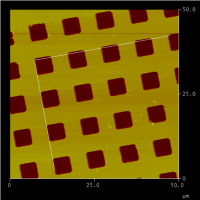
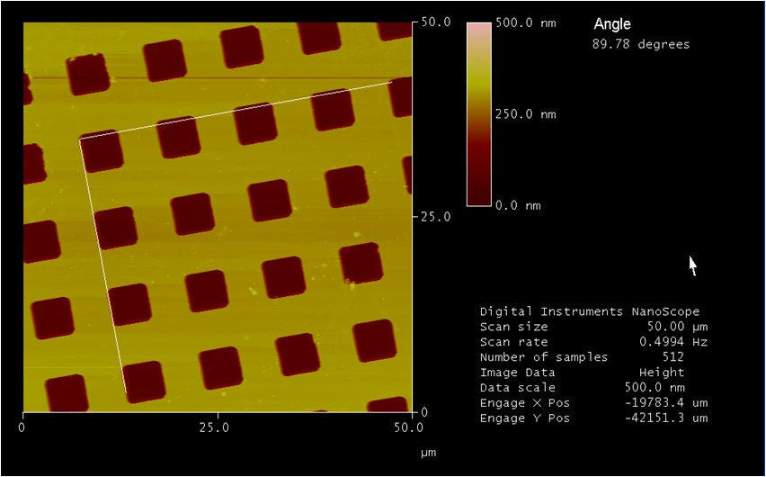
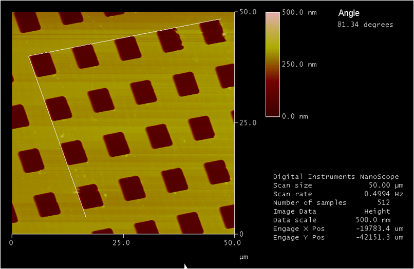
One method to measure orthogonality error is to acquire an image of a calibration grid. The image below is a 50µm scan of a 10µm calibration grid. The scanner has very good orthogonality but can still be used to demonstrate that one can easily change the orthogonality behavior via nPoint GUI.
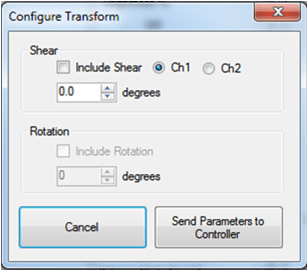
Using the nPoint application GUI one can enter the number of degrees they wish to change the orthogonality. The interface is simple and is shown below. The user can pick either axis (X or Y; Ch1 or Ch2) to “sheer” by a certain amount. The rotation capability will be available in upcoming versions.
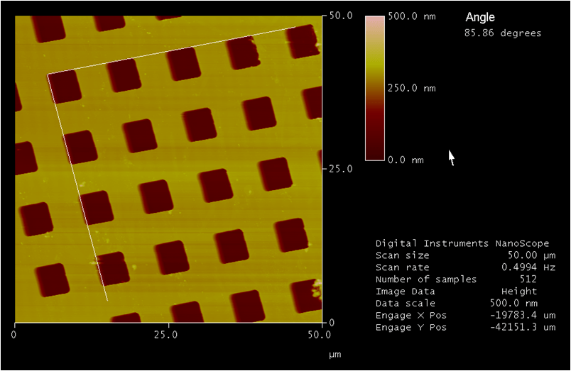
We use the same grid and apply a 4˚ sheer (Fig. 3a) and a 9˚ sheer (Fig. 3b). The images below demonstrate this.
The orthogonality correction demonstrated above is just one example of what would generally be called a co-ordinate transformation function. Such function can be used to sheer one axis with respect to the other (as demonstrated), to rotate the coordinate system by a certain angle, to map three planar actuators into an X, Y, theta configuration or three Z actuators into a tip, tilt and Z movement combination.
To achieve such co-ordinate transformations the nPoint DSP controller does not treat each piezo driver and sensor circuit as part of a single physical axis but rather performs a linear mapping using multiple channels. The output of the control loop is transformed back into the real world system to run the individual physical axes.