This article provides data that demonstrate the capability of nPoint controllers to integrate with quadrature sensor signals for closed-loop feedback. In some applications using an external sensor such as an interferometer can be essential in order to compensate for drift or maintain position in an entire system. Adding this capability eliminates the need for internal sensors such as capacitive or strain gauge sensors. The user can still take advantage of all the features of the nPControl software (such as built-in function generator, notch filter programmability, etc.) even though the closed-loop functionality is provided by an external sensor.
Note: Some graphs may be hard to read as thumbnails. Please click on the images to see in a detailed view.
A. Equipment and Set-up
The following equipment was used to collect the data in this report:
1. NPXY100-100
2. LC.403 controller with 3-channel encoder interface
3. Renishaw RLE20 laser interferometers with REE interpolators. One of the interferometers was used as the sensor for closed-loop feedback while the other was used to monitor the position. The REE interpolator for the closed-loop sensor was plugged in directly to our encoder interface in the LC.403. Typically a 2m cable would be provided to connect the REE interpolator to our encoder interface (longer upon customer request).

B. Data
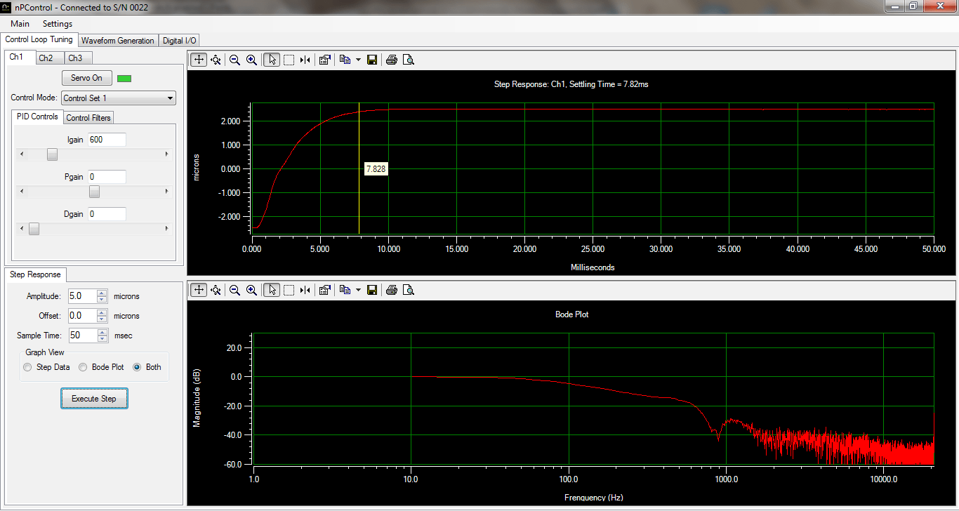
When the encoder is used for closed-loop feedback, the capabilities of the nPoint controllers are still available via the nPoint GUI, nPControl. The user can perform open and closed-loop step response, vary the control gains, program notch filters, use the built-in function generator, etc. The sensor displayed in the GUI is the encoder. An example of an open-loop and a closed-loop step response is shown in figure 2.
B.1 Step Response


Figure 2. Open-loop (a) and closed-loop (b) step response. The encoder sensor data is displayed in the nPoint GUI.
B.2 Position Noise
While in closed-loop with the laser interferometer we perform an RMS noise measurement on the position of the NPXY100-100. The value measured is approximately 0.015 nm. The peak-to-peak position noise displayed in the GUI is shown below. The divisions (scale) on the y-axis in figure 3 is 0.5 nm.

B.3 Repeatability
The stage is commanded to perform 50µm steps in either direction from the “center” position. The stage is in closed-loop using head 1 as the sensor. Interferometer head 2 records the data that is displayed below.

B.4 Position Measurement/Use of nPControl Function Generation Capabilities
The stage is commanded to move via the built-in function generator of the LC.403. Its position is measured by head 2 and is displayed in two different cases: 1 Hz, 100 µm triangle wave and 100 Hz, 0.7 µm sine wave. In the case of the 100 Hz sine wave the resulting motion is less due to bandwidth limitations. The data is shown in figure 5.


B.5 Linearity and Repeatability of Motion
The stage is commanded to move 100 µm and the position is recorded with head 2. The linearity and hysteresis over 100 µm is shown below. The linearity deviation is within 10 nm over 100 µm and the hysteresis is within 5 nm over 100 µm.

External sensors can be used as direct closed-loop feedback for nPoint piezo stages. If you have any questions please contact nPoint!